Variable Mutual Conductance Compressor
Transformerless Tube Compressor


Gain Reduction Meter schematic

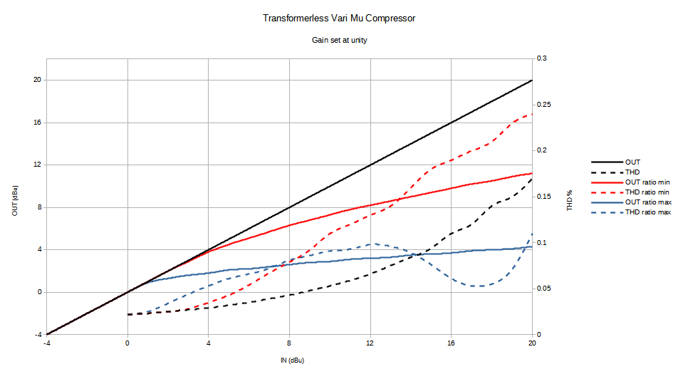
Compression Curves and THD @ 1kHz
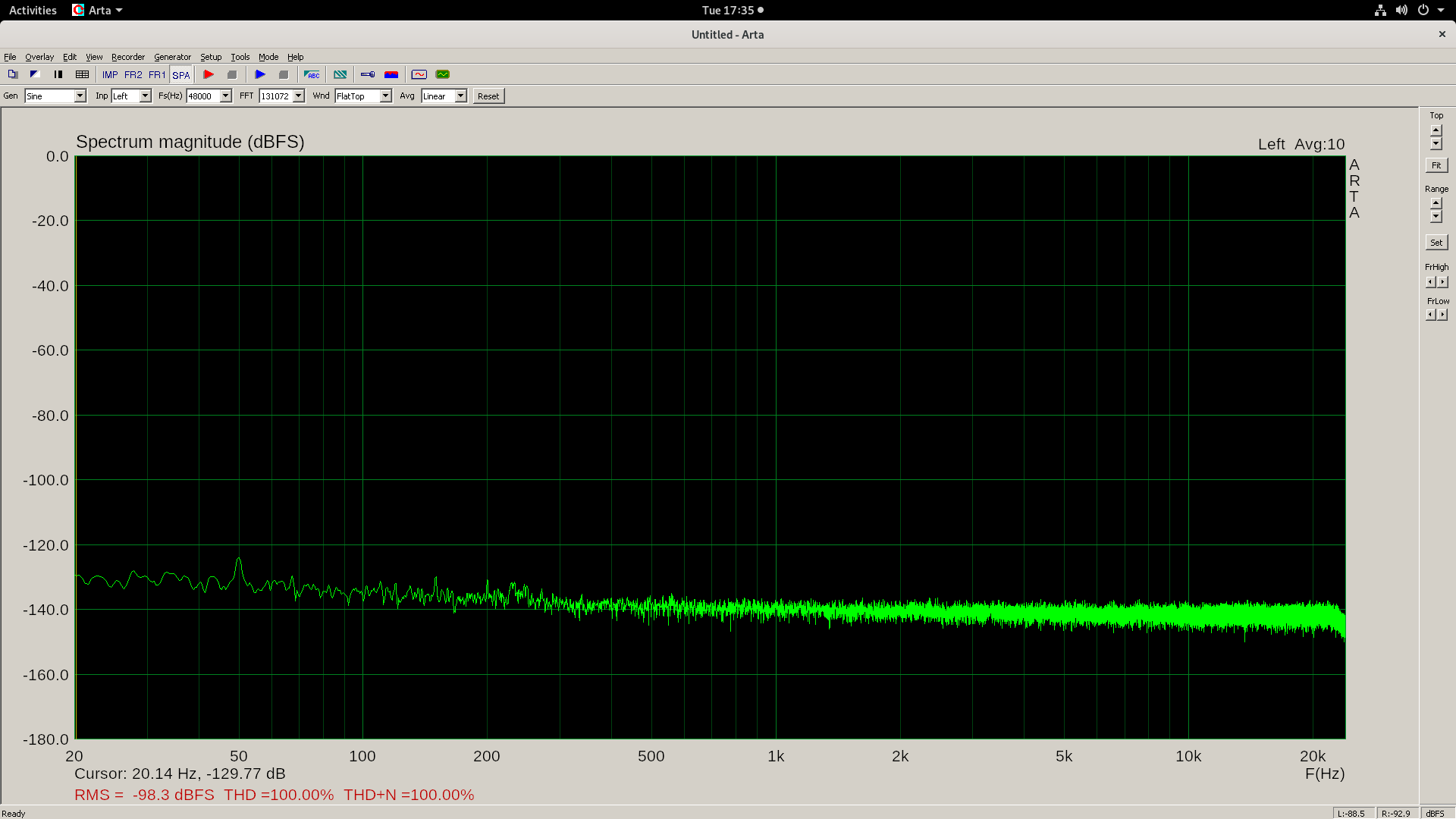
Output noise at max gain (19 dB), 0 dBFS = +20 dBu
Specifications:
Input impedance ≈ 12k ohms, balanced line-to-line, *
THD < 0.25%, +20 dBu, 20-20 kHz, unity gain, no compression, **
S/N = 80 dB re +4 dBu, 22 kHz BW, unity gain, ***
Crosstalk = -60 dB, 20kHz, +4 dBu, channel-to-channel
Frequency response = 20 - 20 kHz, ±0.5 dB
Maximum gain = 17 dB or 19 dB, ****
Output impedance < 300 ohms, balanced line-to-line
* INA2137 Internal resistors are ratio matched but have ±25% absolute value
** Will heavily depend on the tubes used
*** Should be better than 80 dB unless the tubes are very noisy
**** Will depend on the tubes used and plate resistor value used. 19 dB with 5.5k plate resistors, 17 dB with 4.99k plate resistors
If the output is connected to unbalanced input do NOT ground xlr pin 3. For unbalanced connections output XLR pin 3 should be left floating, this will result 6dB loss of output level.
Further reading:
Graeme - Applications of Operational Amplifiers 3rd generation techniques. Pages 52-53 (pdf pages 70-71)
Audio line receiver impedance balancing using a 2nd diff amp
Compression and Limiting, Elements of sound recording by John G. Frayne and Halley Wolfe.
Säätöputkikompressorit (in Finnish)