Tube Compressors
Principle of operation
In tube compressors, compression is achieved by means of vari-mu tubes – also called variable‑mu, remote‑cutoff, or super‑control tubes. The gain of the amplifier is adjusted by varying the grid‑bias voltage of the remote‑cutoff tubes. When the control grid voltage is made more negative with respect to the cathode, the tube’s anode current and transconductance drop.
The circuitry of the compressor does not differ much from a conventional push-pull amplifier, but it has an added control circuit (sidechain) that creates a variable grid bias voltage for the tubes (control voltage). Figure 1 shows a simplified block diagram of the compressor, from which the essential parts for compression can be seen. U1 and U2 are remote-cutoff tubes that form a push-pull amplifier. The transconductance of the tubes, and thus the gain, depends on the bias voltage of the control grid. Therefore, it is a voltage-controlled push-pull amplifier. A variable grid voltage is supplied to the control grids through the centre tap of the input transformer T1, which is connected to the anodes of the diodes D1 and D2. The audio signal is fed to the cathodes of the diodes. The threshold level is set by the forward‑voltage drop of the diodes and the voltage adjustable by potentiometer RV1.

When a signal is fed to the input, the compressor works like a typical amplifier and amplifies the signal. However, if the signal is large enough, diodes D1 and D2 begin to conduct. Signal peaks that exceed the forward voltage of the diodes charge capacitor C1 with a negative voltage. The voltage of capacitor C1 determines the grid bias voltage of tubes U1 and U2. The more negative the control‑grid voltage, the smaller the gain.
Figure 2 shows an example of the input/output characteristic curve of the compressor. Until the signal exceeds the threshold, the compressor behaves like a linear amplifier; beyond that point, compression begins and the amplifier’s gain falls. It is also common for tube compressors to have a compression ratio that varies with the amount of compression. Therefore, the ratio of the compression slope is gradually softer (soft knee).

The compressor’s attack time is set by how quickly capacitor C1 charges. The attack time can be expressed as an RC time constant, where C = C1 and R represents all series resistance with C1, including the output impedance of the amplifier that drives the diodes. The release time is expressed by the RC constant of C1 and R1. However, there is no standard for how compressor attack and release times are specified.
After the voltage-controlled push-pull amplifier, there may be one or more additional amplifier stages. The control circuit may contain its own amplifier stages to generate the control voltage, or, in a compressor with multiple amplifier stages, it may derive the control voltage directly from the anodes of the last push‑pull stage. A good example of a compressor with only one amplifier stage and a separate amplifier for the control voltage is the Fairchild 660. An example of a compressor that does not have a separate control amplifier is the RCA BA-6A.
Tube compressors are generally known as Vari-Mu. The name Vari‑Mu suggests that the tube’s gain factor (mu) would vary. However, the gain factor stays nearly constant even under large anode‑current changes, whereas the transconductance (gm) and anode resistance (ra) vary significantly. The operation of Vari-Mu compressors is based on the change in transconductance, not on the change in gain factor. The gain factor also changes with the anode current to some extent, but never enough to be useful.
There are also tube compressors, such as the TRIMAX A.30, in which a series resistor and the tube's cathode resistance form a voltage divider, and the signal can be attenuated by changing the tube's bias voltage. The operation of this type of compressor is also based on the change in transconductance. As with transconductance, anode resistance is also a function of the control grid voltage. In a triode, with a small grid bias voltage, the anode resistance is relatively small, and as the grid bias voltage is changed to be negative, the anode resistance increases. In this way, signal attenuation can also be implemented using a voltage divider formed in the anode circuit. The amplifier's gain can also be controlled by a feedback circuit. The feedback circuit has a tube whose anode resistance determines the amount of negative feedback in the amplifier. However, most tube compressors are implemented with a vari-mu circuit, and this is generally considered the best way to implement a tube compressor.
Distortion in Vari-Mu Compressors
Traditionally, achieving the best results required a push‑pull, transformer‑coupled voltage‑controlled amplifier. In a push-pull amplifier, even-order harmonics of distortion cancel each other out, although not perfectly, and with transformer coupling, a common-mode DC change does not reach the output or the next amplifier stage.
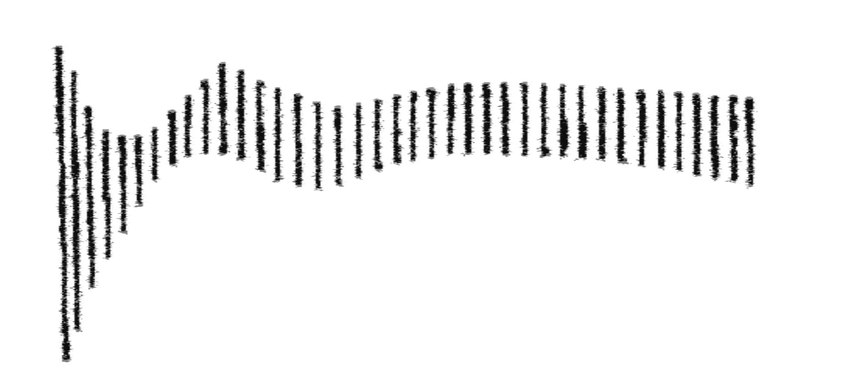
The grid bias voltage is changed by the control circuit, and the control voltage on the grids can be many times larger than the audio signal. The control voltage changes the tube's anode current abruptly. If the anode currents of the tubes in the push-pull amplifier are not balanced, rapid changes in anode current can cause a low-frequency transient ("thump" sound) at the output. Achieving perfect balance is impossible, but with good matching, the signal-to-"thump" ratio can be made sufficiently large. In a poorly balanced compressor, large signals with fast attack times can also be over-compressed, i.e., attenuated too much. After this, it takes some time for the amplifier to stabilize and the signal to return to the correct level. In the worst case, the return to the correct level can take tens or even hundreds of milliseconds. With sufficient tube matching and a good control circuit design, over-compression and "thump" sounds can, however, be prevented. Figure 3 illustrates what can happen to the signal in a poorly balanced compressor.
The RC circuit does not completely filter the control voltage to a pure DC voltage. The variation in tube bias voltage caused by the ripple voltage modulates the signal, causing distortion. This distortion cannot be eliminated even with perfect tube matching. This distortion appears at low frequencies and increases as the frequency decreases. For this reason, when compressing material that contains a lot of low frequencies, it is advisable to use slow release times.
Total harmonic distortion and intermodulation distortion depend on the amount of compression. The distortion is caused by the fact that the anode current is reduced to achieve compression, and the signal is at its maximum in the compressor amplifier stage with heavy compression. In particular, intermodulation distortion can become very high with heavy compression. Many modern tube compressor manufacturers do not specify intermodulation distortion at any compression levels, because a high IMD value with only a few decibels of compression does not look good in the device's performance specifications.
Matching the remote-cutoff tubes is very important to ensure that both halves of the push-pull amplifier are as balanced as possible. The matching should remain good across the range of anode currents. Tube compressors usually have one or more balance adjustment trimmers, with which the balance can be fine-tuned.
Tubes in Vari-Mu Compressors
The less the transconductance changes with the anode current, the more linear the tube is. In a compressor, the gain is desired to change with the anode current, so a tube with changing transconductance is needed. In conventional (sharp-cutoff) tubes, the anode current drops rapidly with the grid voltage, and a small current and large signals are not a good combination. In remote-cutoff tubes, the tube current does not cut off even with large negative grid voltages.
Compression can be implemented with triode, pentode, or heptode tubes. The advantage of a heptode is that the audio signal can be fed to a different grid than the control voltage. In a pentode, the control voltage can also be fed to the screen grid, and the audio signal to the control grid, which has a fixed grid bias voltage. When the control voltage is fed to a different grid than the audio signal, the problem is that the compression amplifier overloads with large signals. the best results are typically obtained when both the audio signal and the control voltage are applied to the control grid. The control voltage can also be fed to the tube's cathode; in this case, the control voltage is positive. In the age of electron tubes, it was not practical to feed the cathode, because the cathode impedance is very low, while the control grid impedance is very high. Nowadays, with a semiconductor-based control amplifier, the control voltage can be fed to the cathodes, and in this way, the need for an input transformer can even be eliminated.
The manufacture of remote-cutoff tubes has been discontinued, except for the JJ 6386 double triode, but the availability of many NOS tubes is very good. Russian versions of the 6SK7 and EF93 pentodes are available at very low prices. However, it is not necessary to use remote-cutoff tubes. For example, the 12AU7 double triode has been used in several new tube compressors instead of remote-cutoff tubes.
The difference between a conventional tube and a control tube can be seen in Figure 4. In the 6SJ7 tube, the current cuts off at a grid bias voltage about five times smaller than in the 6SK7 tube. The characteristic curve of the control tube is very nonlinear, and therefore is not suitable for an audio-frequency amplifier. In radio receivers, the grid bias voltage is changed according to the radio station being received, and the nonlinearity is beneficial, because the transconductance changes along the entire curve, and the current does not cut off. At radio frequencies, the distortion caused by nonlinearity is insignificant, because the tube's load is a tank circuit. However, if remote-cutoff tubes are used as audio amplifiers, then the push-pull circuit operates linearly.

Designing Vari-Mu Compressor
The tube gain Av = gm * rp||RL, where gm is the tube's transconductance, rp is the anode resistance, and RL is the load seen by the tube. If a pentode is used as the tube, then the gain Av ≈ gm * RL, because rp ≫ RL.
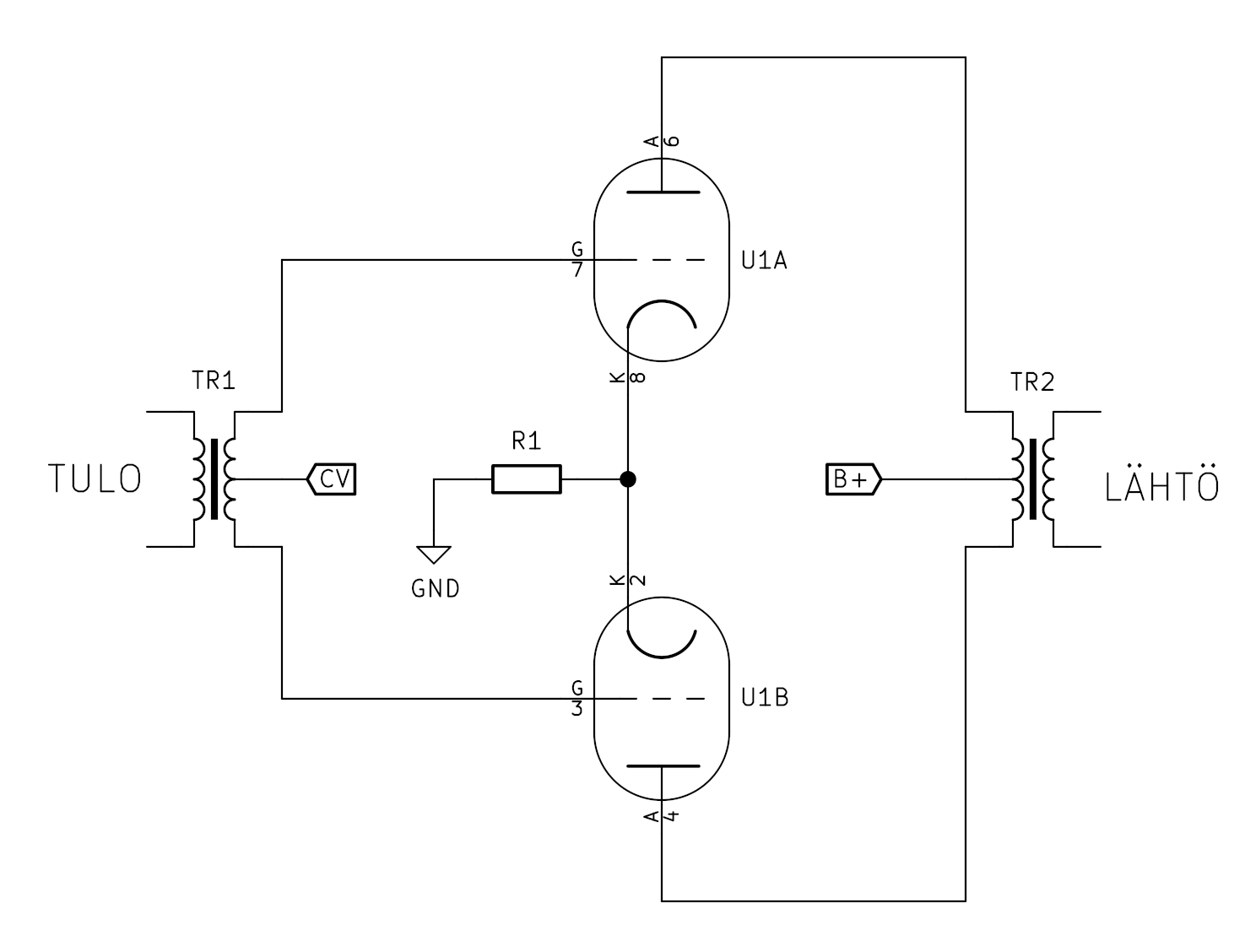
Figure 5 shows a typical way to implement a voltage-controlled tube amplifier. A disadvantage is that the source resistance and the primary inductance of the transformer form a high-pass filter.
The output transformer TR2 is perhaps the most demanding part of a tube compressor. In the transformer's primary, the source resistance and the inductive reactance of the primary form a voltage divider. As the frequency decreases, the reactance decreases, and the voltage in the primary decreases. At the frequency where the inductive reactance and the source resistance are equal, the signal is attenuated by 3dB. The anode resistance increases as the anode current decreases, and the transformer's primary inductance must be large enough so that low frequencies are not attenuated during compression. The transformer must also tolerate DC current in the primary, otherwise the transformer core will saturate and the inductance will drop if the tubes are unbalanced.
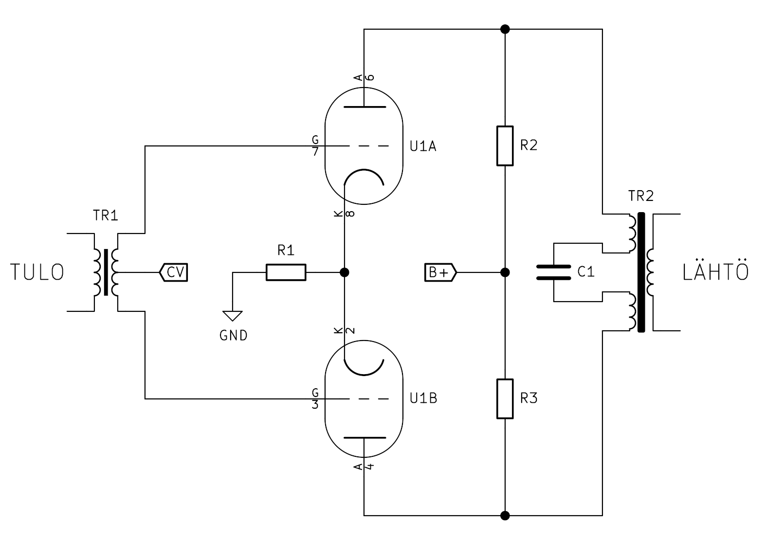
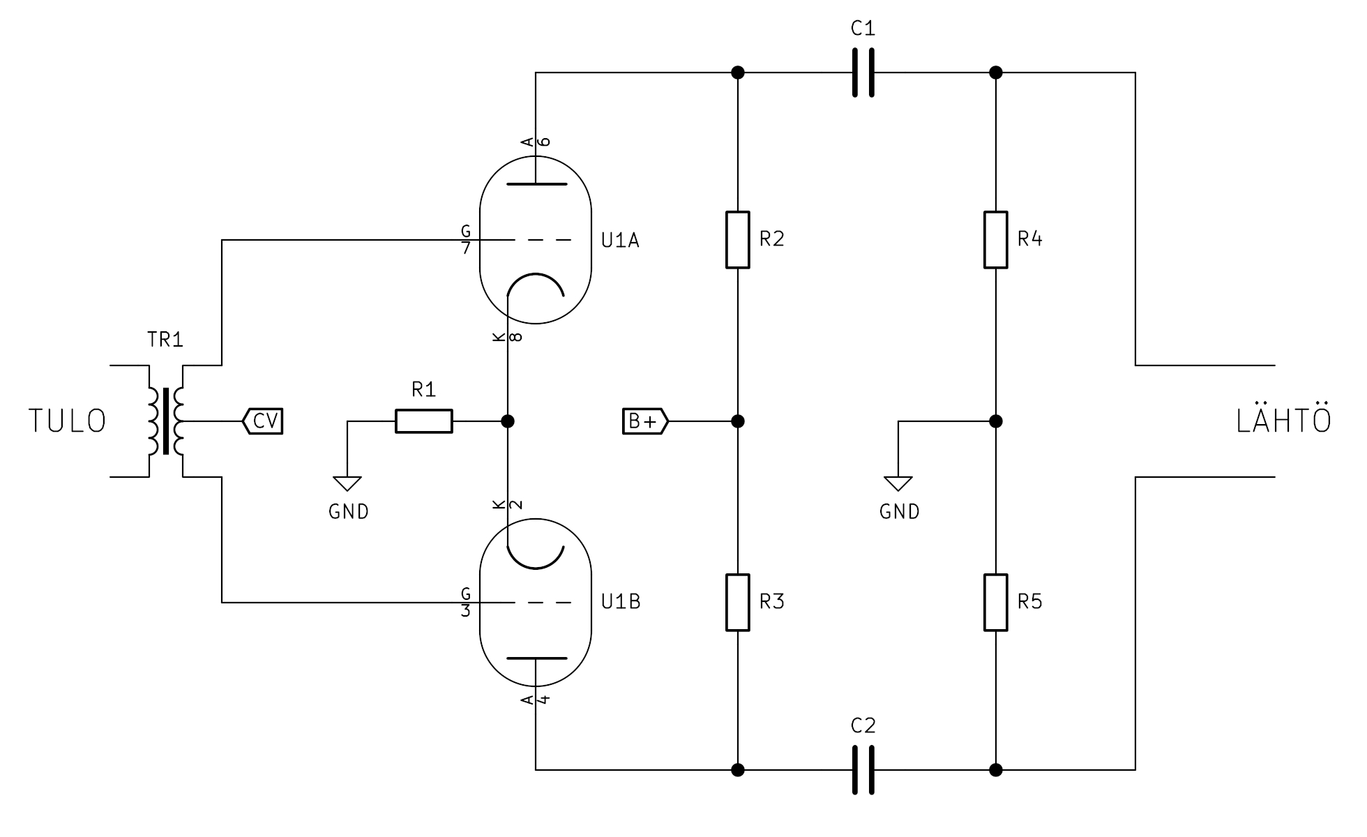
In Figure 6, DC current is kept out of the transformer using capacitor C1. By keeping DC current out of the transformer, even a poor balance of the tubes will not cause attenuation of low frequencies. The anode resistors R1 and R2 determine the maximum source resistance with which the transformer is driven. In this circuit, the load seen by the tube is the transformer's reflected load in parallel with the anode resistor.
However, it is not necessary to use a transformer at the output of the compression amplifier; an RC circuit can also be used. The problem with an RC circuit is the large common-mode voltage that is transferred to the next amplifier stage.
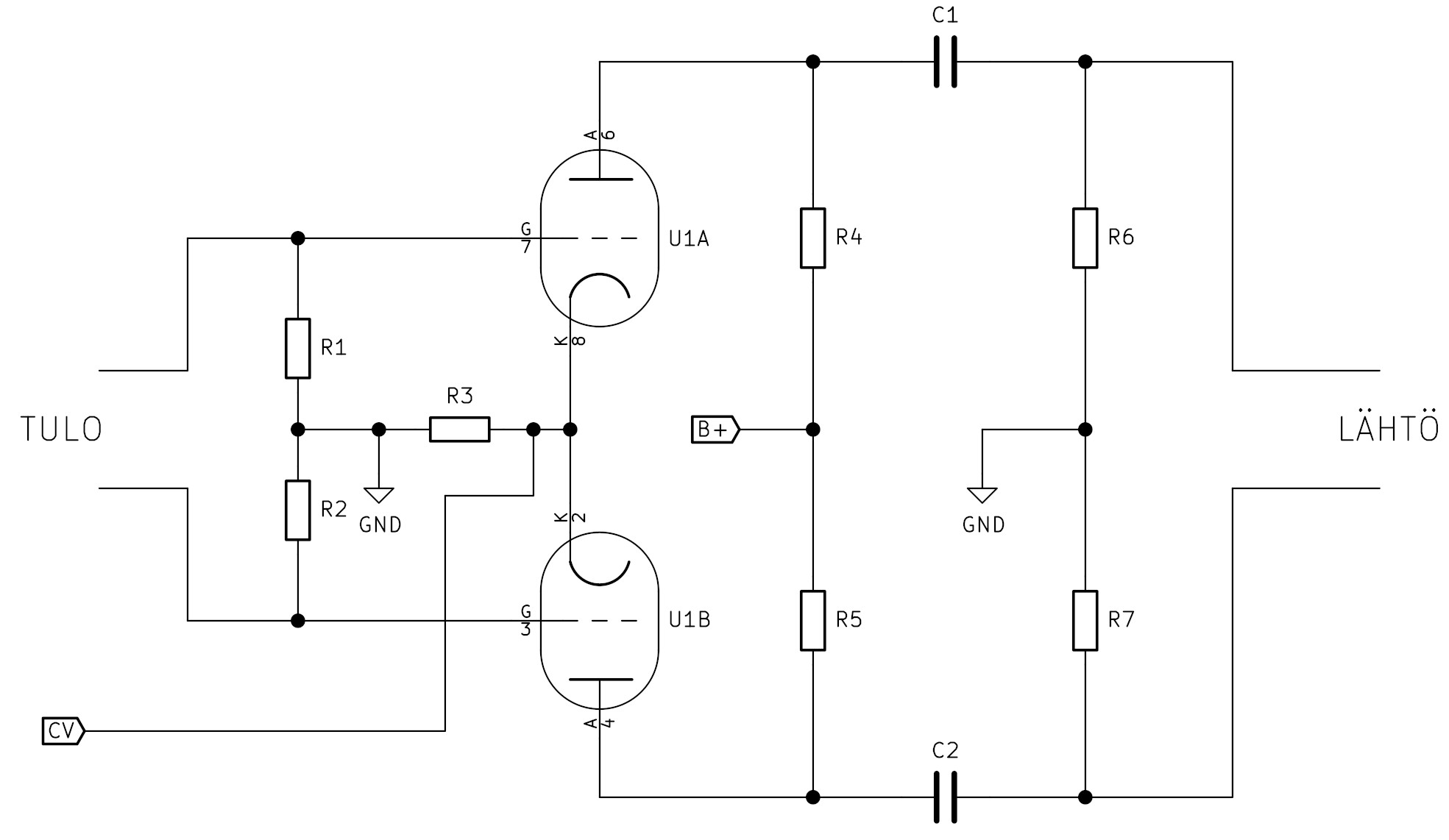
In the circuit shown in Figure 7, if the anode current of both tubes is 5 mA, and the anode resistors R2 and R3 are 10k, and for example, during compression, the anode currents drop to one milliampere, this will cause a 40V common-mode voltage. The next amplifier stage requires a high common-mode rejection ratio and the ability to handle large common-mode voltages.
Transformerless Vari-Mu Compressor
Tube compressors are generally expensive. The high price is largely due to the expensive audio transformers. A mono compressor has 2 or 3 audio transformers, and a stereo compressor has 4 or 6 transformers. However, the number of transformers can be reduced if semiconductors are used in the control circuit and in some of the amplifier stages. Traditionally, the input to the compression amplifier stage has a transformer. The input transformer provides a symmetrical input signal to the compression stage and the impedance for the control signal is practically infinite. The input transformer can be eliminated if the control voltage is fed to the tubes' cathodes. When fed to the cathodes, the impedance for the control voltage is low, so the control amplifier must be implemented with semiconductors.
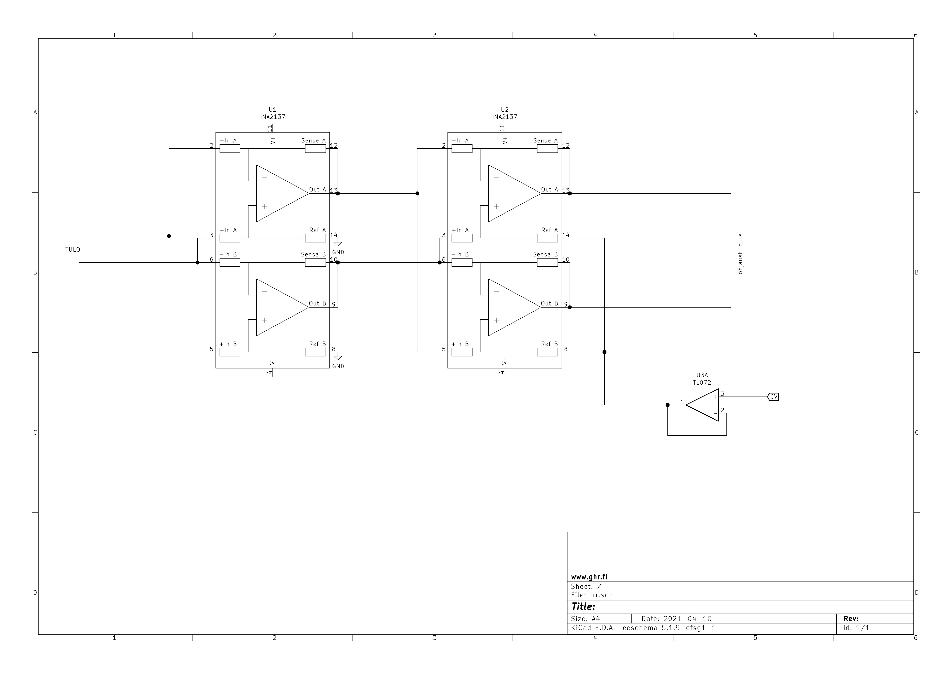
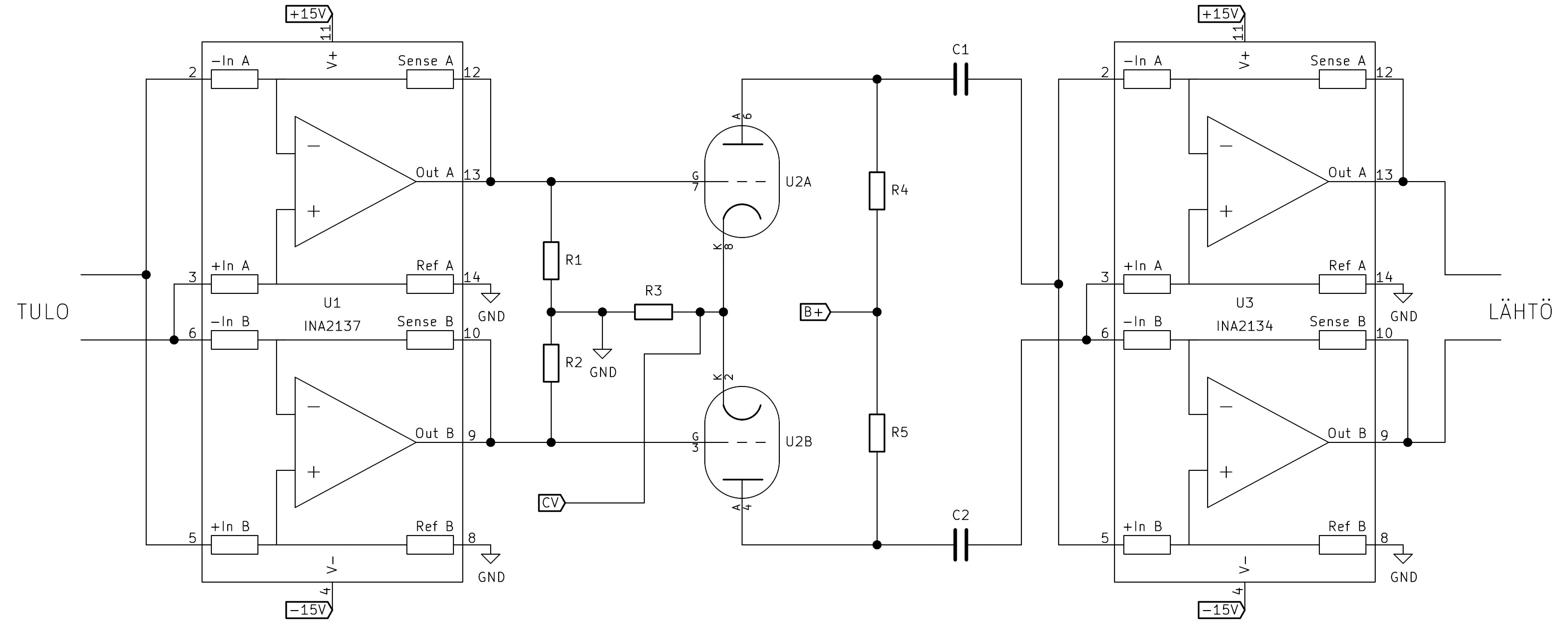
In Figure 8, a symmetrical audio signal is fed to the grids without a transformer, and the control voltage is fed to the cathodes.
When the control voltage is fed to the cathodes, the input transformer can be replaced with a cross-coupled INA2137 differential amplifier. The output transformer can be replaced with a cross-coupled INA2134 differential amplifier. The maximum common-mode voltage at the inputs of the INA2134 is about 25V, so the common-mode + differential voltage must be kept below 25V, or the amplifier will overload. The common-mode rejection ratio of the INA2134 at low frequencies is 90dB, so it attenuates common-mode signals almost as well as a high-quality transformer.
Sidechain
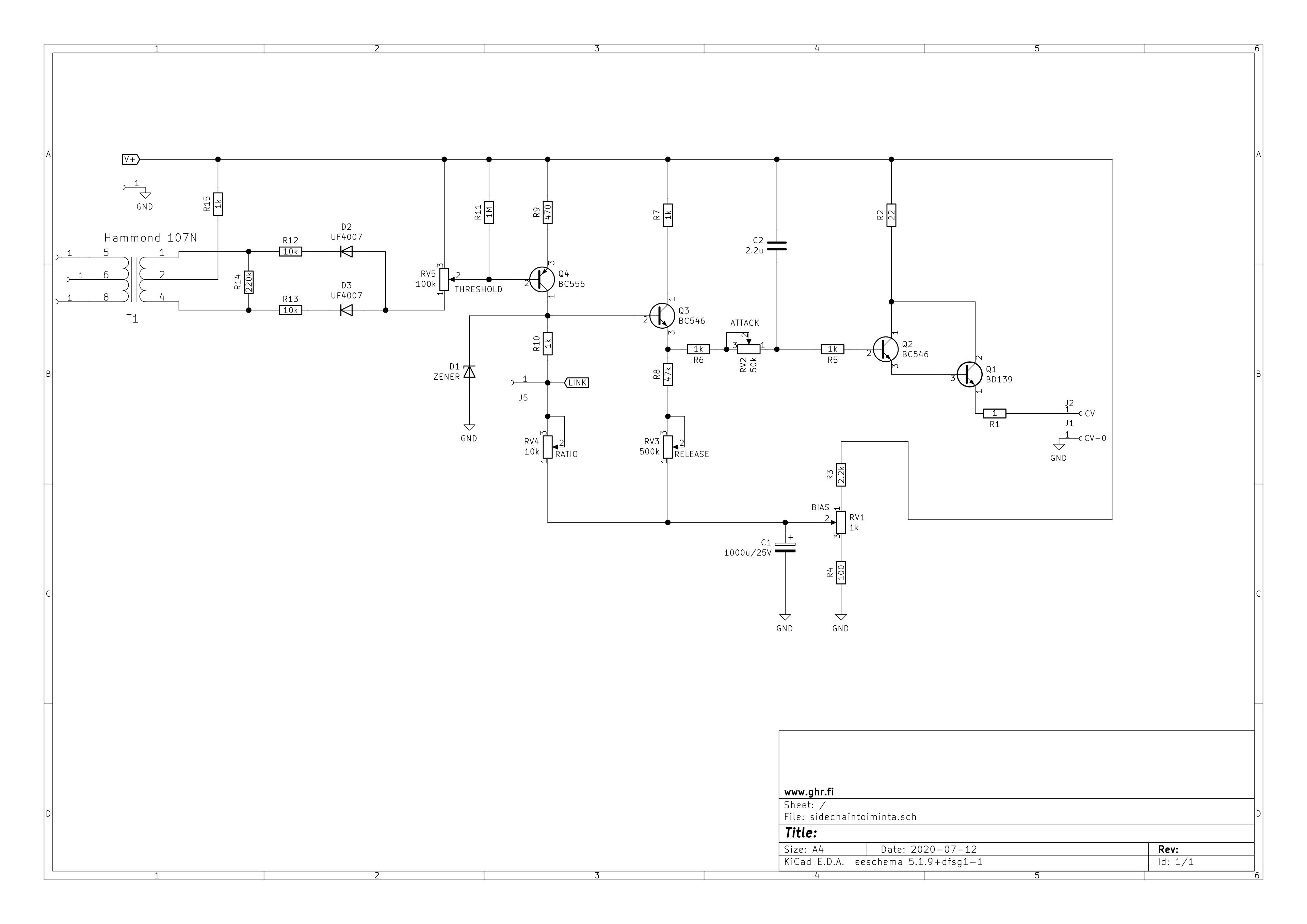
Figure 10 shows the control circuit. The audio voltage is fed between pins 5 and 8 of transformer T1. Diodes D2 and D3 convert the audio voltage into negative pulses with respect to the voltage V+. When the negative pulses exceed the base threshold voltage of transistor Q4, Q4 amplifies the signal and inverts the pulses to positive. Potentiometer RV4 can change the amount of amplification of transistor Q4. Transistor Q3 acts as a buffer. The pulses charge capacitor C2 to a positive voltage. R6 + RV2 determine how quickly C2 charges, and RV3 + R8 + R6 + RV2 determine how quickly C2 discharges. Transistors Q2 and Q1 form a Darlington circuit from which the control voltage is fed to the tubes' cathodes.
Traditional Sidechain
However, if the control voltage is to be fed to the control grids and a more traditional control circuit can be used, Figure 11 shows a circuit with which the input transformer can be replaced.